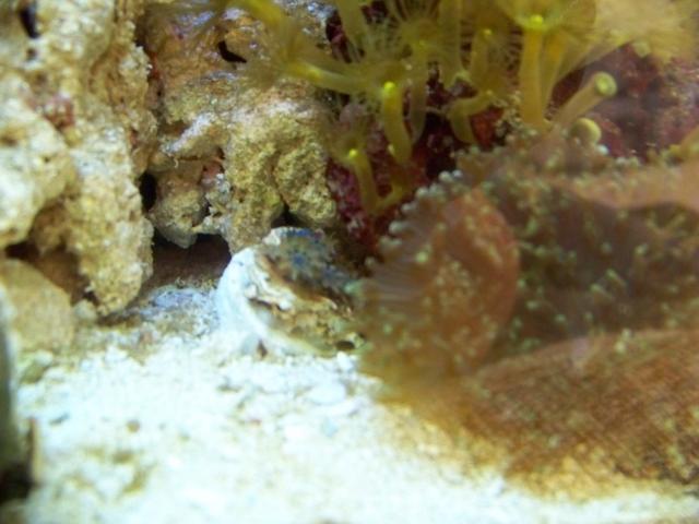
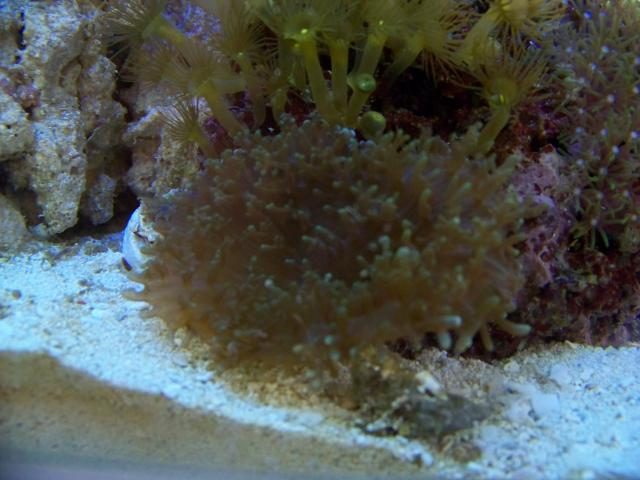
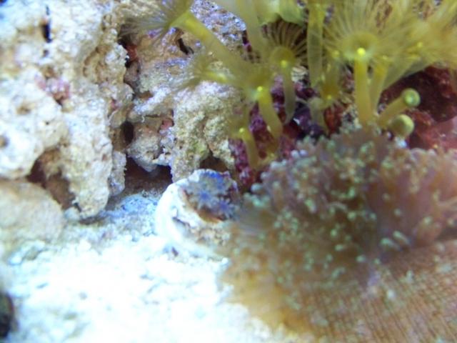
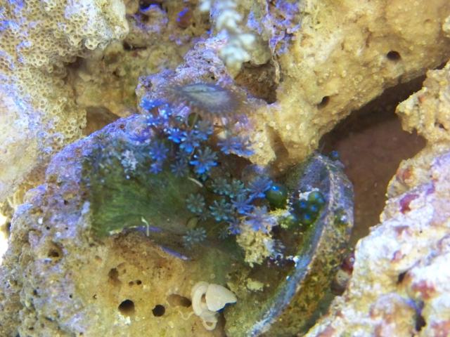
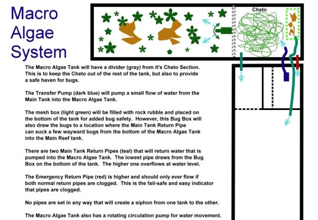
|
|
|
|
|
|
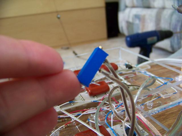
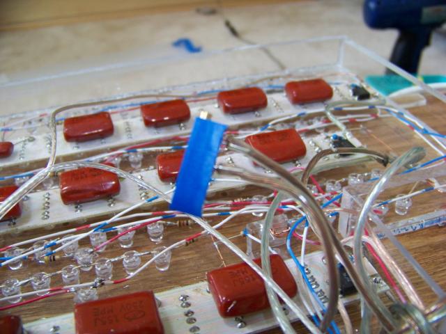
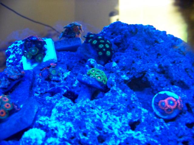
To keep the lights from shocking the corals, I added a dimmer to the blues so that I can slowly turn them up more and more over about a month.
|
|
|
|
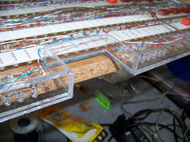
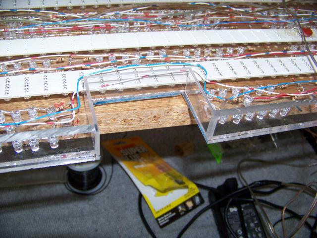
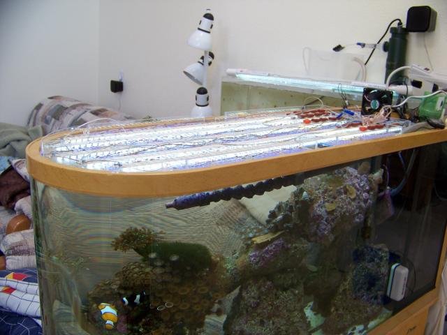
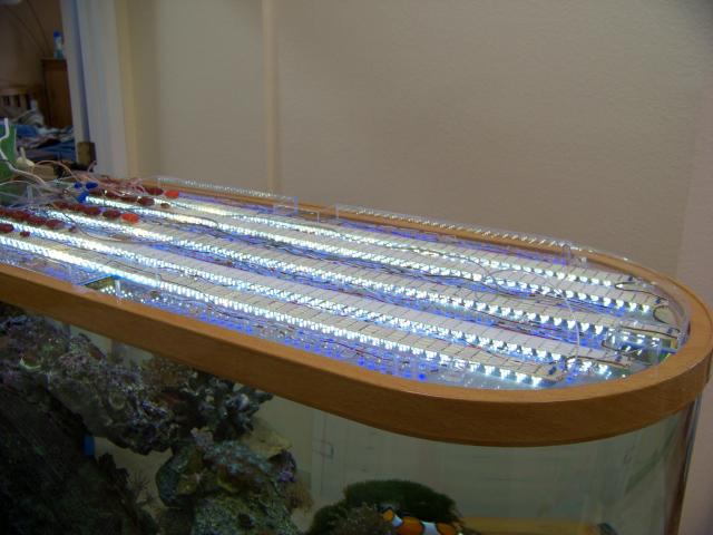
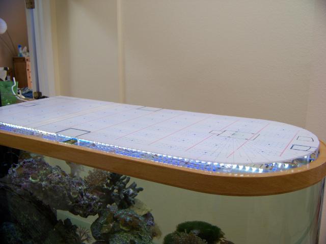
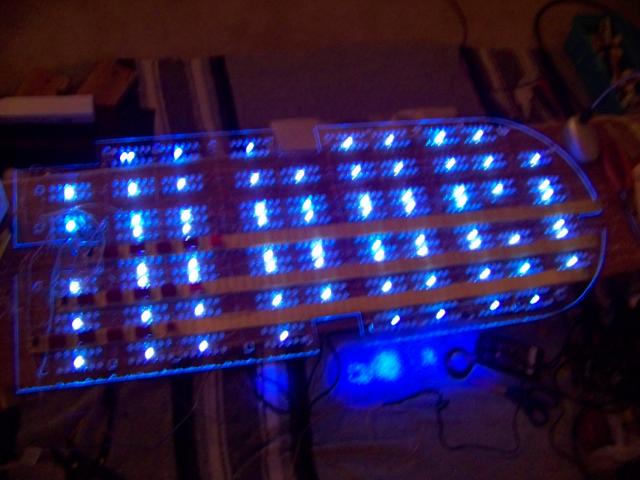
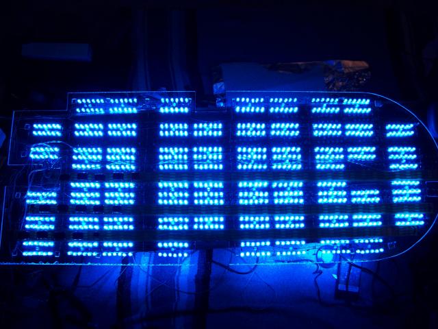
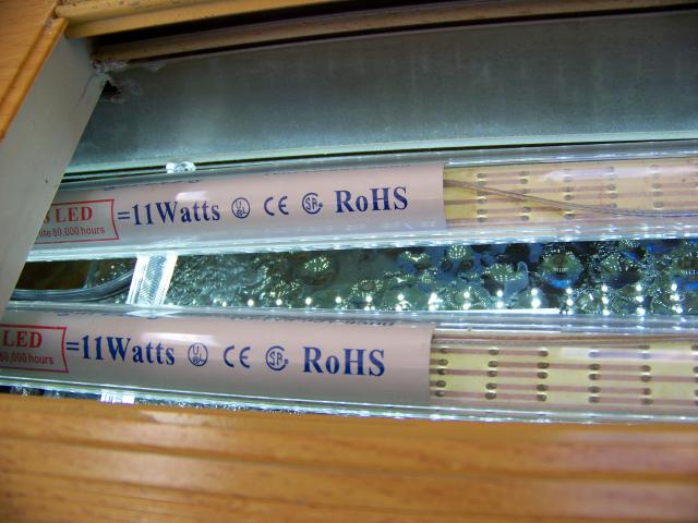
Light goes all the way to the front and is even across as well.
|
|
|
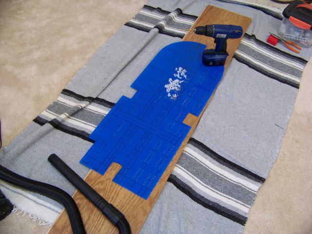
I still have to do the cutouts in the cover, but thought I should double check the placement of the cuts first.
|
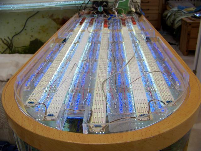
First cut out 'hatches' for accessing tank and marked lines for the blue LED holes and space for the white LED strips that will sit on top.
|
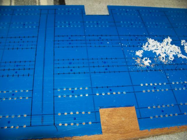
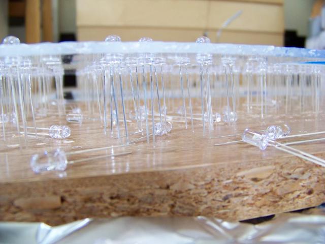
756 holes for Blue LEDs and 71 holes for UV LEDs.
Total: 827 holes.
Boy am I glad I don't have to do the white LEDs individually as well.
|
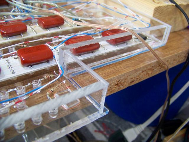
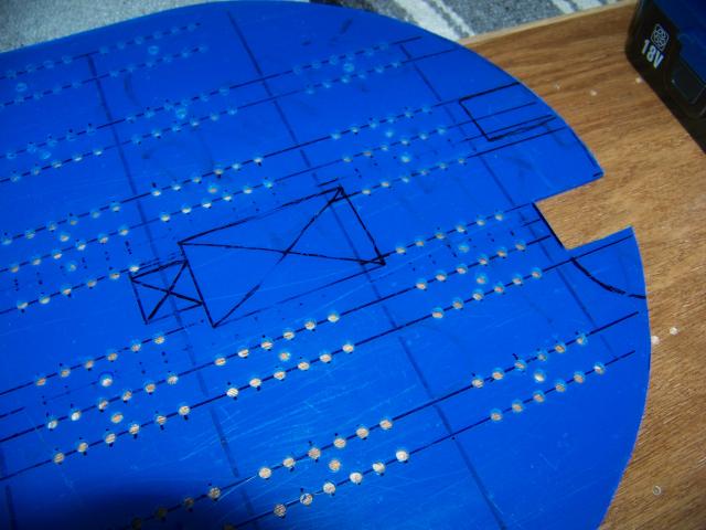
While the 'wave' pump in the nose of the tank will be attached to a different piece of plexi over the tank, area was left open of LEDs since light won't be needed on top of the pump.
|
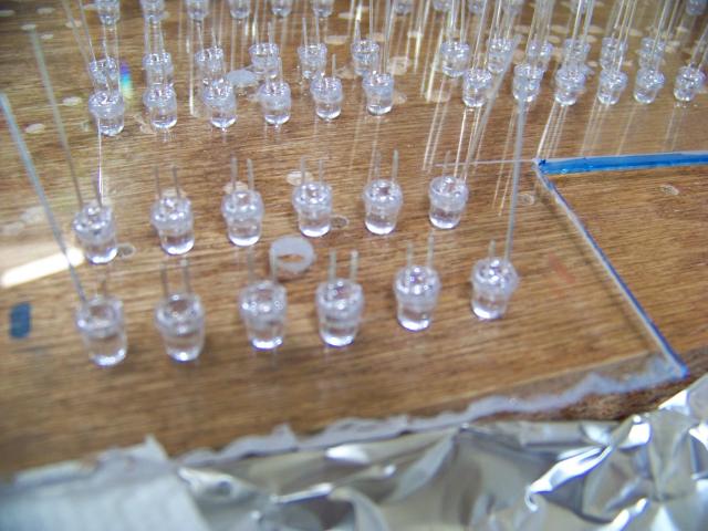
I thought that the LEDs were made of a type of acrylic that would bond to the plexi with a special chemical, so I added each LED with the chemical to bond it. A lot of work, but worth it for a solid bond........ right?
|
Turns out that it is not the same and doesn't bond... I will have to add super-glue to the top and bottom edge of the LEDs to seal them in later. Wish I had known this to start with, but the test I did seemed to bond... realized later that it just melted the plexi around it tight enough that it apeared bonded.
|
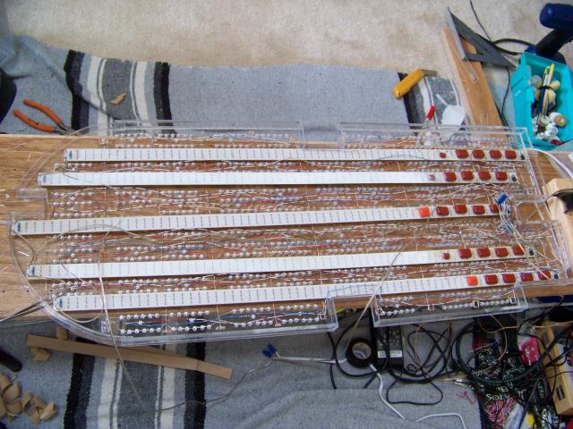
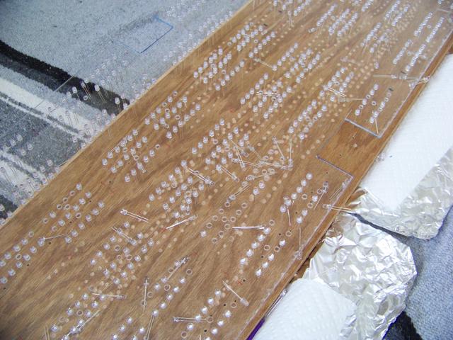
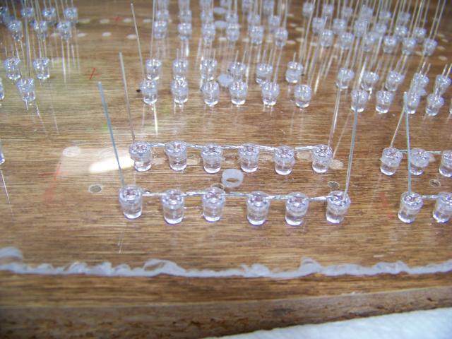
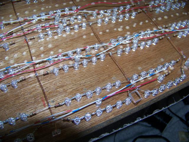
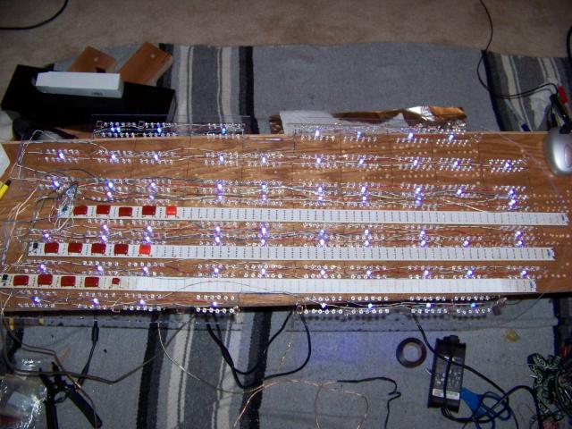
Each LED prong (except the end prongs) must be cut to fold right against the next LED in line in a set of 6. (Determined by the power supply I will be using.)
|
Each LED has a long prong and a shorter prong so that you can tell the positive and negative ends. In sets of 6 they were folded positive to negative to create a complete line. After soldering the connections, I tested each set and only had a few that needed an LED replaced or re-soldered.
|
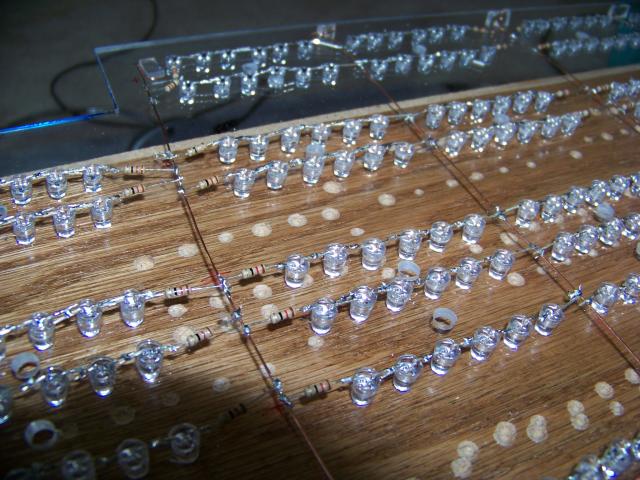
The Copper lines will be my main positive and negative lines and were added by streaching a line between two glued on pieces of plexi. This made a pretty firm line to be able to solder the negative prongs onto and positive line to resistor to prong.
Each row of parallel 6-sets shares a negative copper line with the set in one direction and a positive copper line with the set in the other direction.
|
The UV LEDs run on their own power supply that requires two LEDs connected per resistor. These LEDs have to have insulated 'jumper' wires attached as positive, negative, and between themselves. It is MUCH harder to solder the loose wires, especially since most of them need two wires and a prong attached at each connection. Even harder on the two wire plus a resistor hair-sized wire.
|
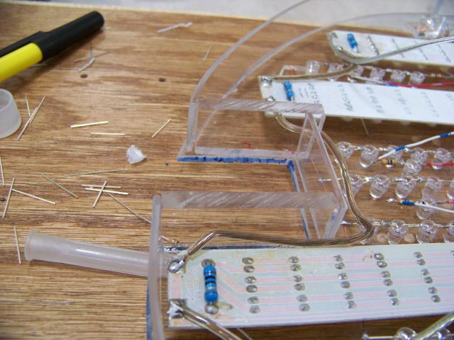
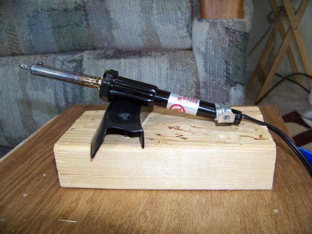
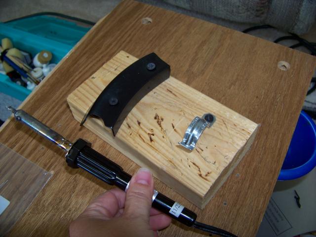
While thin little wire stands are available to rest your heating and cooling solder iron on, I really didn't trust the easily knocked over style.
I made my own stand that locks the iron in place at the base when you slide it in and down as well as providing a plastic raised rest to keep the heated metal section raised away from any surface.
|
The cord slides under the metal bracket at the bottom, then the lower handle can be moved back to lock it in place. However, it is still easy to slide up and out with one hand when needed.
|
|
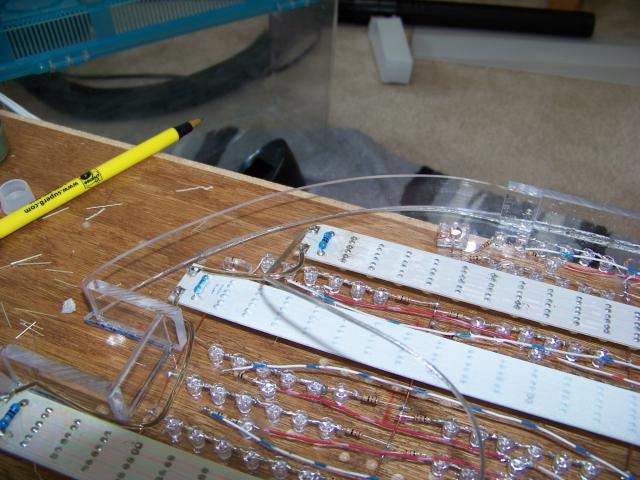
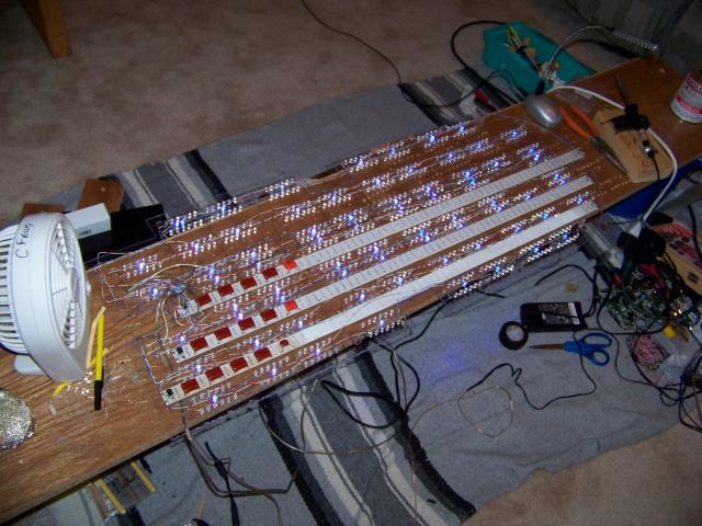
Still need to secure the white strips to the plexi and add their power supply.
|
|
Had to re-solder just a couple connections that had bumped loose while adding the UV lights, but they are all working now.
|
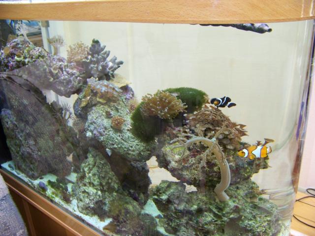
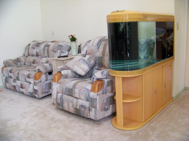
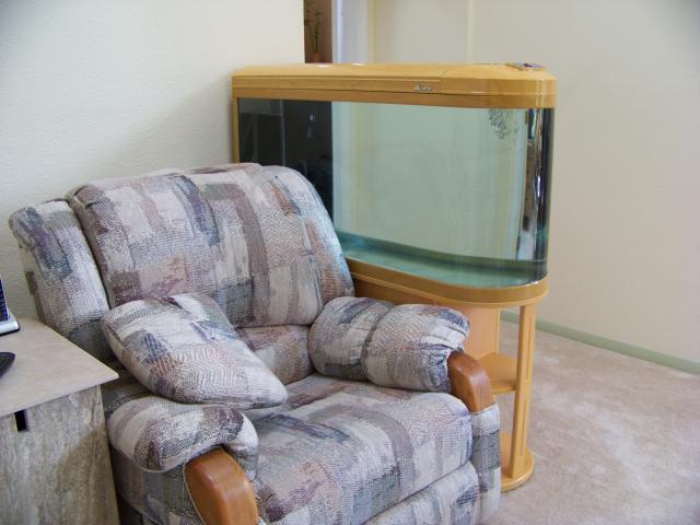
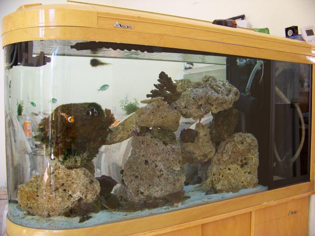
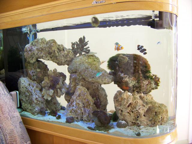
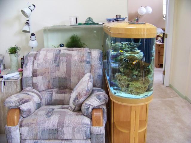
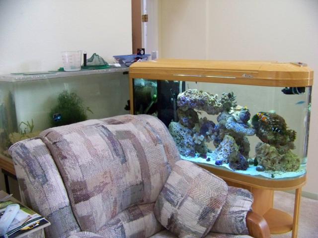
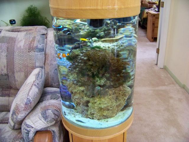
I finally got the 90 bullet tank we have had for 3 years patched on the back and set all up. It leaked the first time, but this time it seems to be holding fine.
|
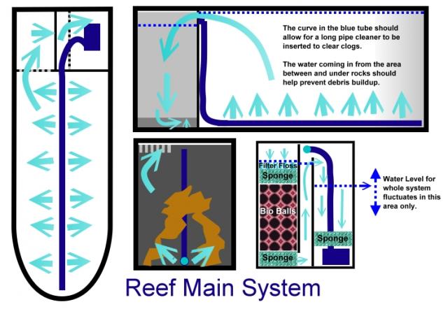
As soon as I find my salinity measure thing, I will begin adding salt to it. It has an inner black chamber in the back that will act as the sump and filter area in addition to the filter that is built into the hood.
| Album By: Tally and Chris Fells
|
|
|
|
|
|
|
|
|
|
|
|
|
|
|
|
|
|
|
|
|
|
|
|
|
|
|
|
|
|
|
|
|
|
|
|
|
|
|
|
|
|
|
|
|
|
|
|
|
|
|
|
|
|
|
|
|
|
|
|
|
|
|
|
|
|
|
|
|
|
|
|
|
|
|
|
|
|
|
|